Categories
Praxis Devblog

Rules and Visual Syntax in Praxis

version 0.1.0 This post will explain the most common activity in Praxis; making rules, and also how the visual logic works. Try Praxis live, at: https://toblotron.com/praxis/0.1.0/ (Not mobile friendly)

How to make a rule

Rules in Praxis are constituted of different shapes that are connected together, or placed inside each other.

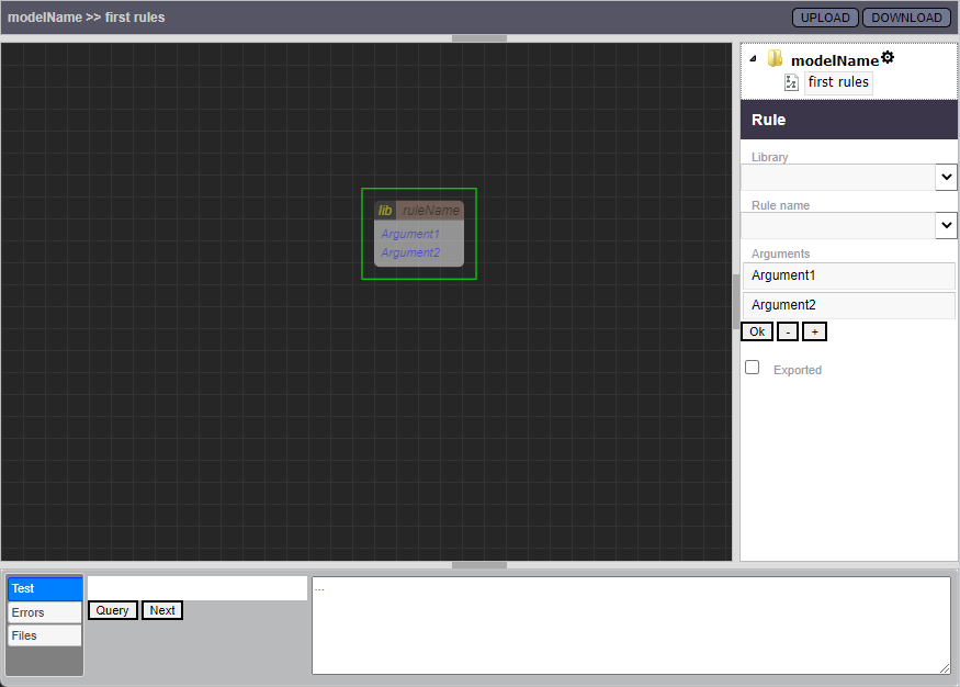
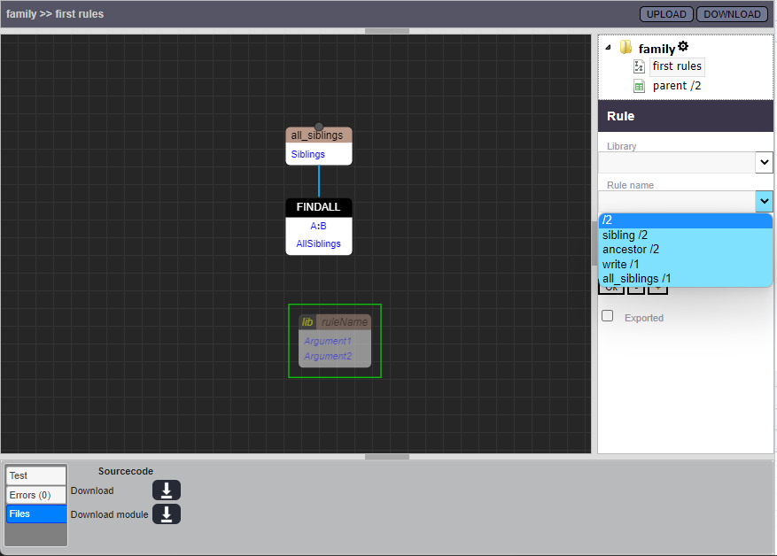
To create the most basic kind of rule, just drag out a Parameter shape from the palette and fill it with the rule name and arguments.

Shapes can always have connectors going in or out at the top or the bottom. If there is a Parameter shape with no connection coming in from the top (and which is not contained in a Group), Praxis will make that shape into the “head” of a new rule.

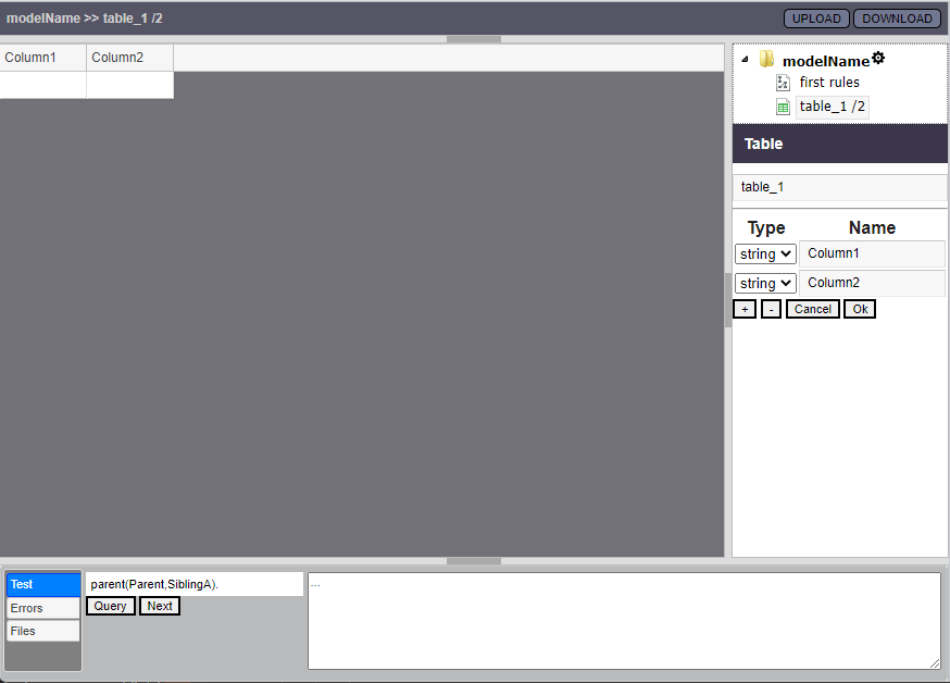
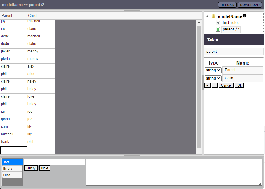
If there is nothing connected to the bottom of the Parameter shape, the rule will have no “body”, and we will call it a “fact”. (though usually we prefer placing our facts in tables, since they are so simple).

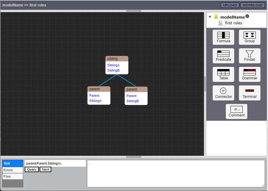
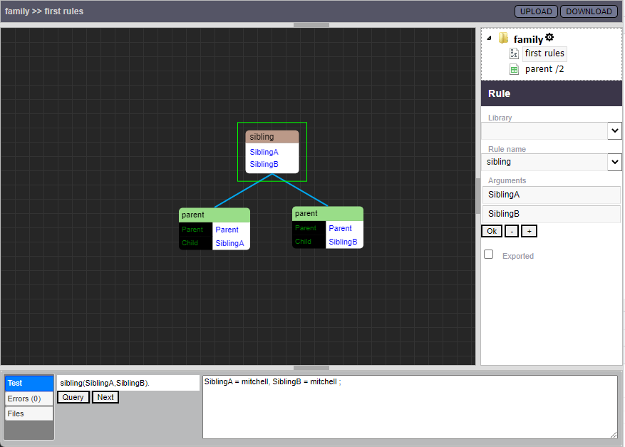
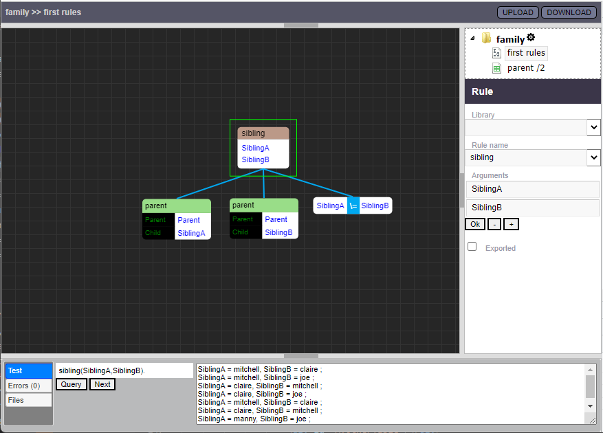
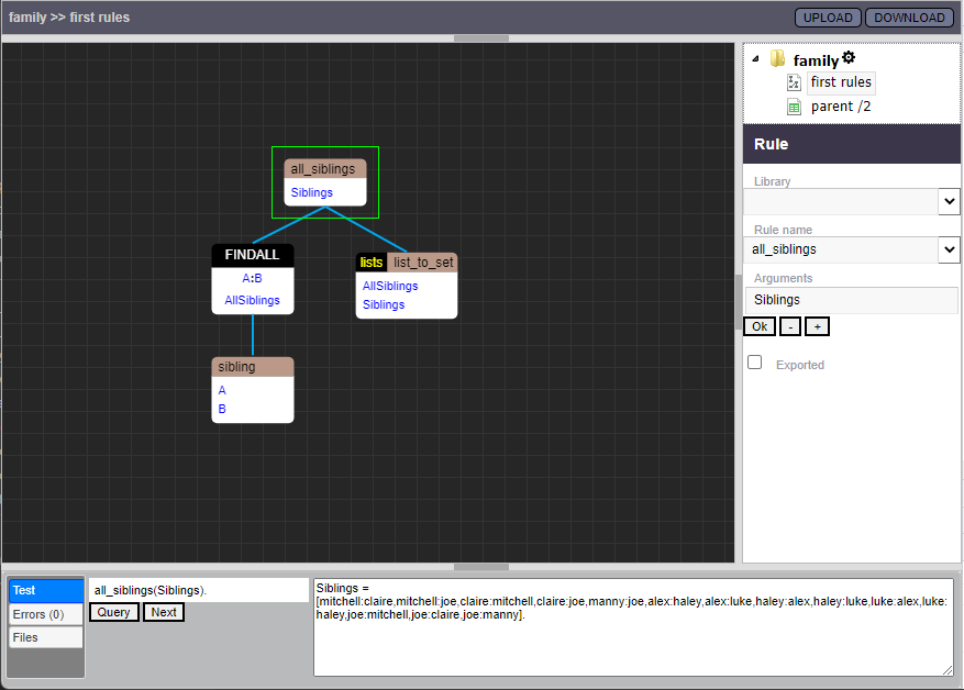
Here we have added a “body” to the head of our rule.

Order of execution within a rule

So, when we have a bunch of shapes connected – how is it decided in which order they will execute?

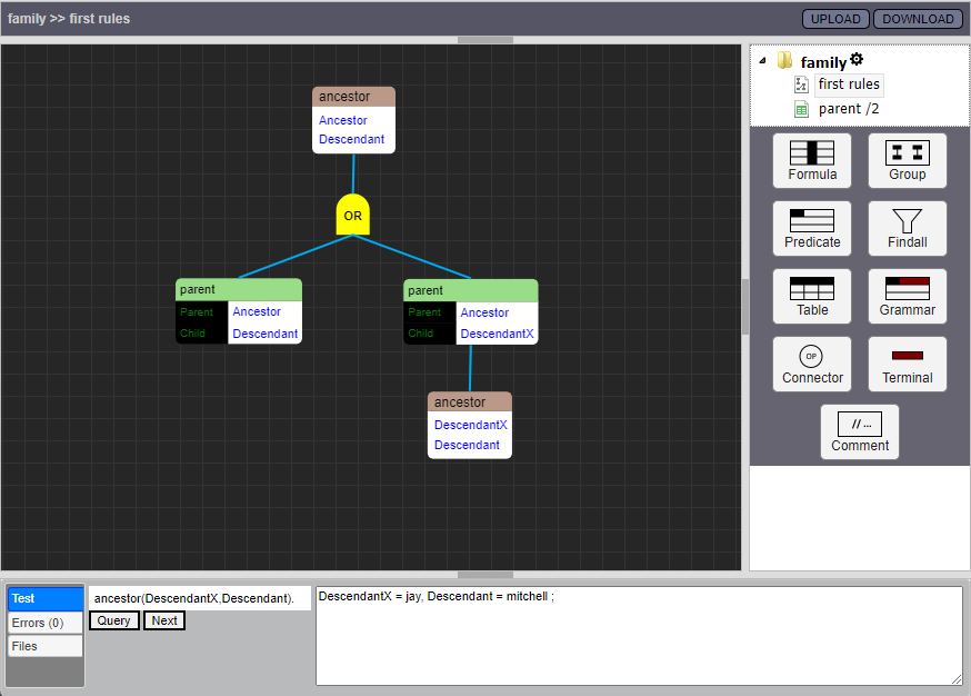
Praxis uses a simple depth-first order of execution, going from left to right if there is more than one child. Let’s look at a simple rule:

  1. We ask the question ancestors(Ancestor, Descendant) – this head matches the query, so we start executing the rule. There is only one shape below;
  2. It’s an OR-connector, which means that we will consider it true as soon as one of its branches is proven true. We test the two “child” branches from left-to right, and arrive at..
  3. A check for a parent(Ancestor,Descendant). If this succeeds the rule has finished, since the OR-connection above will be satisfied, but let’s assume we don’t, so we can go on and test the sibling branch:
  4. Here we ask for some Other child of Ancestor, and if we find one we go on to..
  5. The final shape to be tested. If this call succeeds, the rule is successful.

Order of execution among rules

Usually in Prolog we have several instances of a rule, and they are typically executed in the top-down order they appear in the source-file (text).

In Praxis, we go from left to right, when order among rules on the same page is concerned. Rules that are defined on an earlier page, in the model, will run before instances of the same rule defined on later pages.

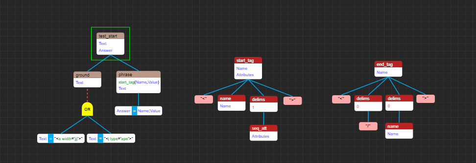
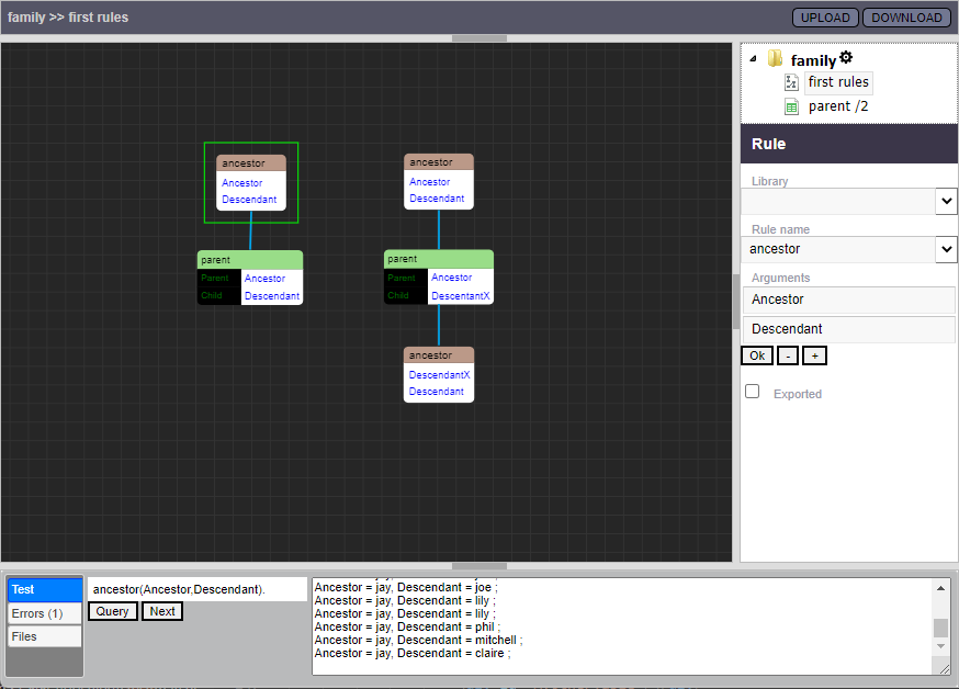
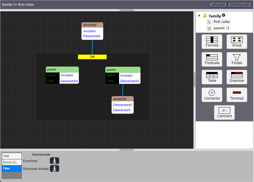
Here we see a more common and “Prolog” way of defining the ancestor/2 rule.

Now we have two separate “cases” of the rule. The rule to the left will be tested first, and the rule to the right will be tested if the first rule fails. This should lead to exactly the same response as with the previous “OR”-formulation.

Groups and Connectors

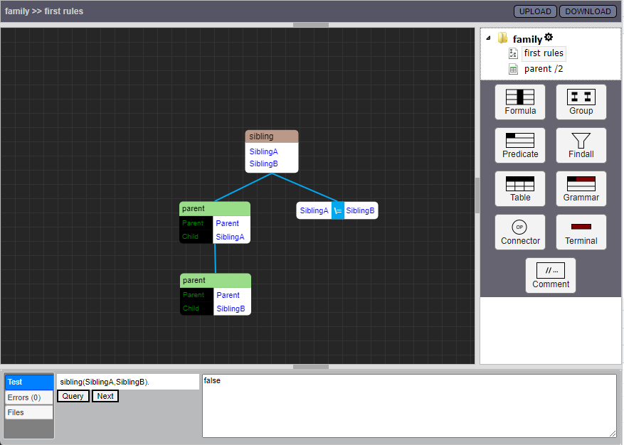
If you only draw (normal) connections between normal shapes, you can only draw rules in which every contained/ connected shape must succeed.

A normal connection between shapes basically states “if the shape above [the connection] succeeded, it is now time to see if the shape below succeeds”, or “if above, then below”.

This is not very flexible, so let’s introduce ways of combining shapes with operators other than the basic “if-then” connections; groups and connectors.

Groups

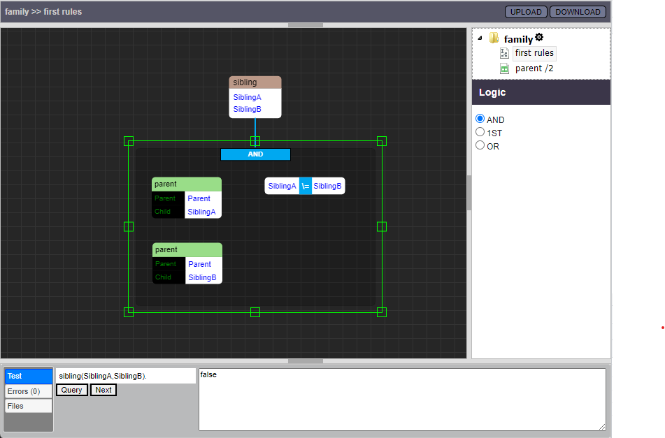
Above we saw an example of the connector-shape, with the “OR” operator selected. Here is the same rule, using a Group instead. (the generated code should in this case be exactly the same)

In what order will shapes be executed within a Group? Well – if a shape (within a group) has no incoming connections, it will be one of the “head” shapes within that Group; it will denote the start of one of the alternative branches (or “siblings”) within that group. If a shape within a Group Has an incoming connection, it will not be executed until the shape connected to it from above has been proven successful.

The order of execution here is exactly like in the example with the OR-connector, above.

Groups can also contain other, smaller Groups.

One neat thing about Groups is that there can (like for all other shapes) be connections below them, which means that those shapes connected below will be executed After the Group has succeeded. (if it does)

PS – this is not a proper way for a reasonable person to solve “fizzbuzz” -it is just meant as an illustrative example.

Groups (as opposed to connectors, as we will soon see) have only 3 operators to choose from;

  • AND – which is the default; ALL branches inside the Group must succeed
  • OR – which means that ANY, at least One branch must succeed
  • 1ST – or “First”, which means that once a branch succeeds, no other alternative branches will be tried on backtracking. (this interpretation uses the Prolog “if” operator which performs a cut)

PS – I’m not sure if using the “if”, or “->;” construct is a good idea, here – I’ve been looking at alternatives that do not include “cut”, but haven’t landed an any yet. -Keep in mind that it’s early days yet, for Praxis, and very few things are carved in stone

Connectors

Connectors have more operators you can choose from!

In addition to the ones used by Groups, (AND, OR, 1ST) they can also perform:

  • NOT – This will succeed if all shapes connected below are Not successful. This also uses the “if” operator which performs cuts.
  • CUT – or just “!”, in Prolog-speak. This operator has the effect that no other alternatives to decisions taken previously in the rule will be tried during backtracking, once it hits. CUT will always succeed.

(experimental) Else-connections

One of the objectives with this project is to explore the possibilities offered by expressing logic in a 2-dimensional way. One, experimental feature, is the “Else-connection”, which we will have a look at now. (just right-click a normal connection to turn it into an else-connection)

As we’ve said before, the meaning of the “normal” connection (solid blue) is “if the shape above me succeeds, then also try the shape below me”.

The Else-connector (dashed red) instead says “if the shape above me Fails, then try the shape below me”

This makes it possible to draw a kind of decision-trees.

In the same way that All the children connected by blue connectors will be executed when their parent-shape succeeds, All children of red connections will be executed when their parent-shape fails.

In the code, this is (right now) implemented through the use of the “if” (->;) construct, which I am not 100% in love with, since I guess it might lead to strange situations.. do you have any other idea that might work for this? 🙂

Currently, the else-connector only looks at the specific shape above it, and reacts if the statement of that shape is proven untrue. There could also be a variant which looks at the failure of the entire “branch” of the above shape. There remains a lot of experimentation to be done – please tell me what you think!

Categories
Praxis Devblog

[A preview of] Praxis; Visual Programming in Prolog

Version 0.1.0

Praxis is [supposed to become] an online-IDE for Visual Programming in the Prolog language.

This is the introductory post, where I for the first time try to introduce and present it to the Prolog community.

The version that is currently available, though still not super-stable, has most of the basic abilities that I think are needed to introduce the overall concept;

  • Visual modeling of Prolog rules, using a few basic shapes
  • The ability to edit tabular data (facts) in an excel-like interface
  • Ability to arrange pages containing the two above source-types in a tree-structure
  • Saving and loading to local file-system
  • Execution of model in browser, using Tau-Prolog

Features that are still labeled as “experimental”:

  • Visual modeling of DCG-rules
  • Including and using externally defined Tau-Prolog modules in your model

Let’s just have a look at an example

This example is available to try directly in your browser, right here: The Family Example
[RMB] + wheel = zoom
[RMB] + drag = pan

PS – NOT MOBILE FRIENDLY!

The first time you browse to Praxis 0.1.0 you will come to the Settings-page
Name your model, and right-click the navigation tree to create your first rules-page
And here it is! Open the {modelName} branch and select your newly created page. Let’s give it a proper name, in the Drawing panel which is also shown when you select the page.
Let’s create our first rule. Drag out a ‘Predicate’ shape from the palette, and place it somewhere. You will now see a preview version of the unfilled shape, as well as the Rule-panel which lets you edit the contents. Use the [+] and [-] buttons to increase/ decrease the number of arguments you want the predicate to have
There! You can see where this example is heading, can’t you?
After all, who doesn’t need to keep track of their pesky siblings? 🙂 – We haven’t defined any facts or rules named parent/2 yet, but that doesn’t stop us from saying that we wish to use them.

Basic rules in Praxis are constructed like this: A Predicate shape with no incoming connections ( = from above) are seen as the heads of rules.

Although not visible in this image, every shape that can be connected will show gray connection-disks when the mouse is hovering near it. Drag connection-disks to other connection disks where you wish to make a connection.

If there are connections going down from a head-shape, those will constitute the body of the rule. In order for a rule head/other node to be true, it is first matched/ checked for truth, and then all the shapes connected to it and under it are recursively queried for truth.

If there is more than one child, they are always evaluated from left to right. This also goes for the rules themselves.

The meaning of the default connection can be seen as “if the above shape is true, also demand that the below content is true” (but we will soon se that there are other ways of connecting shapes)

The generated code of the above rule will look like this:

 sibling(SiblingA, SiblingB):-
      parent(Parent, SiblingA),
      parent(Parent, SiblingB).
Since parentage is (in this perspective) usually represented by a whole bunch of facts, it would be nice to just make a list of it – so let’s do that, by right-clicking the navigation-tree where we wish to put our new table, and select “add data table”. A new table, with default name and content will be created.
Let’s change the name of the table, as well as the names of the columns. Right now there is no processing of the content of cells, so you must enter valid prolog values, like the atoms here. These names are from a favorite show of mine 🙂
And now let’s get back to our rules-page. We Could use the predicate-shapes we already had in place, but I think it’s a bit nicer to use the specialized Table shape here. Select the table You want to use, and then just fill the fields you want to match.
Nice! Now just click the head-shape, and it will fill the query field in the Test-tab below. Now click “Query” to run the query without any grounded values in the arguments. Oops! We haven’t checked that SiblingA and SiblingB are not the same, so let’s do that next
There – we took a Formula-shape and filled it with the statements we wanted. (no editing help yet, in that shape, so you’ll just have to enter {LeftValue}{Operator}{RightValue}. -Now the result looks a bit better. ..and here I also remembered to give the model itself a better name
However – due to the rules of rule-construction mentioned above, we could just as well formulate the rule in this way, instead, and still have the exact same order of execution.
Or we could use a Group-shape to collect these parts of the body. In this case I’m not sure it the SiblingA or SiblingB will be executed first (= which is further to the left), but that doesn’t matter as long as they are executed before the Formula-shape.
Let’s try the descendants-rule! This looks familiar, right? I’ve made an oopsie in this rule, so I’m getting a few iffy results.. let’s fix that..

PS – one of the first things on my to-do-list is to start parsing all the shape-input properly, into Abstract Expression-Trees (probably through Pratt-parsing), so it becomes easy to catch things like the singleton variables above.

..and at the same time demonstrate the Connector-shape, and how it can be used to get away from all the AND:ing we’ve been doing so far. Now I’ve fixed the faulty variable name as well, so responses are looking more reasonable
We could also do it like this – the connection between the shapes inside this OR-group will make sure the intended order of execution is respected. If we go to the Files-tab in the bottom-bar, we can now choose to download the generated Prolog code:
Pretty simple code, though I’m not trying to do perfect indentation yet. The intention is that Praxis should not do too much fiddling with the normal orde of things in Prolog, though in many places I will introduce “Visually syntactic sugar” if it makes it easier to express things in a visual way
I still feel bad about my messy siblings/2-implementation, though, so let’s make a rule that returns only Unique sibling-relations. Here I introduce the Findall-shape (will also be able to use other variants like Bagof, and what have you). All things connected to the below of the Findall shape will be executed during its search for different answers, so that is something we need to consider, so we don’t get a funny result.

Praxis does its best to be helpful, so it’s remembered that there is a rule named sibling/2, and lets us choose this directly from the rule-name combo.
Findall-branches need some privacy, so we add the call to lists:set_of/2 in its own branch. Note that we can select “lists” in the Library combo of the Predicate shape, and get a list of all the available predicates in that (imported) library. Er.. ok, could you please fix the thing with having both luke:hailey and hailey:luke? Of course I meant that as an exercise for the student 😉

PS – there are still shapes and other feature that I haven’t demonstrated, but this should do as a short introduction of the main ideas behind Praxis. More of the features (in different stages of completion) will be explored in other posts.

What is the point of it?

(this is a question I regularly get when trying to explain why I’m doing this, so let’s do this once and for all :))

Visual Prolog modeling is great stuff, and I miss working with it

Well, I’ve (oddly enough) spent a bunch of years working with a kind of visually formulated Prolog, and I found it surprisingly nice and effective – especially when the IDE is good enough. We were all commited Prologists, but after getting a visual IDE we didn’t touch a text-editor unless we could help it.

We were doing big things – thousands of rules – mainly to do with serious product configuration, or handling loan and insurance issues. The IDE, with its specialized search-capability, error-checking, clear display of logic, and other helpful features, were what made it all feasible and enjoyable in the long run. (This system is still in heavy use, and getting more customers as you read this – I believe a noteworthy percentage of scandinavian banks/ credit institutes are currently using it)

-I think the concept has a huge amount of potential for the future, and I’ve missed working with visually formulated Prolog. As we can see in the rules drawn in the above example, and the generated source-code, the textual representation is of course more succinct, but briefness isn’t all.

We have plenty of space to store data – what we need more of is things that help us handle complicated things, so they don’t overwhelm our brains.

Visual programming, overall, is a happening place, for good reasons

Visual programming seems to be getting a goodly amount of attention right now, and from my experience I would say that Prolog is a language that seems unusually well suited for visual formulation. (why I think so.. well, that’s another series of posts)

Another exanding area – where views are also widely split, is the world of Low Code-systems…

Of course – it’s easy to get overly enthusiastic about the potential for this, like ..practically every proponent of low-code systems have gotten, over that last half-century or so 🙂

Still.. new ideas and systems for this are continually being developed and put into practical use. Systems like Observable and its ilk actually seem to be fufilling some of the promise of making programming more accessible, and though flowchart-tools have gotten a pretty stale reputation, new Visual Business Process-modeling systems seem to be gaining more and more access to the inner sanctums of corporations.

To me it seems that Prolog (in many ways) would be an excellent language for doing systems like this – especially with the increasing tolerance for heterogenous stacks, as long as the systems can talk REST or similar.

Potential applications for Praxis (even in the short term) in this area can be things like:

  • Make a generic Javascript UI-page that can display flexible forms that automatically let you interact with your Prolog model though normal web-UI controls (this is also great for testing and development)
  • Make a generic REST-server-component where you can just “publish” your models, and they automatically present their exported predicates as endpoints.

(PS – both these things will be well served by a system for modeling with structured data through imported schema-files, which is one of the most important future features on my inofficial roadmap)

There are So many interesting things to do with this kind of technology

A thing I’m aiming for, overall, is to make rules as easy to formulate, utilize, understand and navigate as possible. Formulations can vary; visual rules (in drawings), or visual facts (in tables) – the common denominator is that the simplest and most easily understandable way possible of presenting and editing things is used, and that we can model things in representations that are the correct ones for the task at hand.

Other ways of formulating knowledge that Praxis could (and probably will) use:

  • Hierarchical decision tables, for cases where that kind of reasoning is practical
  • Visual directed graphs; in this paradigm we could specify the parent/2 -facts with viual entities named “jay” or “mitchell”, having directed parent-connections between them

Things on my immidiate roadmap

  • Parsing of all Prolog statements into Abstract Syntax Trees; currently nothing is checked – this will make it easy to add a lot of warnings and error-messages
  • Handling structured data by importing schemas. – When integrating with the outside world we’ll want to be able to speak their language, and that means being able to work comfortably with any kind of DTO they can throw at us. -This means we need “classes” with defined fields- at least for organizing data.
  • Match-connections: Connect different fields in different shapes and matching the connected data. Will make it possible to (for example) have a predicate shape calling findall/3, and linking argument #2 to a branch of code that will constitute the executed contents of the findall-call. If carried to extremes, would make it possible to dispense with named variables entirely.

Well, I think that’s it, for now. This post was probably too long already a few pages ago 🙂

Hope you find this interesting, and that you feel free to ask me any questions or tell me any ideas that happen to pop into your head!